The Quest for Secret JTAG Registers
Introduction
This article looks at brute-forcing a JTAG TAP on a Renesas microcontroller to find secret registers for a proprietary debugging interface.
How Did It Come to This?
After inadvertently destroying a microcontroller in an expensive piece of hardware, I realized I needed more hardware hacking practice on cheap targets. I looked for the cheapest, modern ECU I could find on eBay and ended up with a used controller for a 2017-2021 Suzuki GSX250R. The security of this ECU is of no interest to me as it has no wireless connectivity (which is a good thing) so I’m not reverse engineering it to find CVEs. The goal here was just to improve my PCB depotting, component identification, microsoldering, and firmware dumping skills.
After successfully depotting the PCB, I identified the largest SMD component on the board which was labeled MH8115F. Initial research identified this as a Mitsubishi microcontroller intended for automotive applications. However, more digging revealed this forum post that indicated it was actually a Renesas SH72531.

After matching up the pins, it clearly is just an LQFP176 package of the SH72531. This is good news because there’s no public datasheet for the MH8115F, but there is a public datasheet for the SH72531.
Pulling up this datasheet, I found that it had a JTAG port. JTAG was originally designed for boundary scanning which means triggering and checking pins on different components to validate the integrity of PCB traces. However, the specification for JTAG makes it easy to extend it for other uses. Of particular interest to hardware hackers is the debug functionality often implemented through JTAG ports on microcontrollers which can frequently be abused to dump ROMs for firmware reverse engineering.
Although only the boundary scanning on the JTAG port of our SH72531 is publicly documented, more research reveals that these same pins are used for something called H-UDI which is a debugging protocol. This could be what we need to dump the firmware, but the implementation of this protocol is secret. The supported way to use it is to buy a $1,500 E10A-USB debugger.
I wondered if it would be possible to reverse engineer this protocol with only publicly-available information and the controller I own. First, I needed to understand JTAG a little better though.
JTAG Crash Course
Overview
If you want a deep dive on the JTAG protocol, I would highly recommend this article by Aliaksandr Kavalchuk. The basic idea is that different components on a PCB have TAPs (Test Access Ports) whose behavior is defined by the IEEE 1149.1 JTAG standard. By connecting to these TAPs you can use them for boundary scanning or accessing extra functionality implemented by the manufacturer. These TAPs can be daisy-chained together so that a single set of test pads on a PCB can access the TAPs of every component.
Registers
Every TAP has an Instruction Register (IR) that performs an action and/or selects a Data Register (DR). For example, an extremely common (although optional according to 1149.1) command that can be specified with the IR is IDCODE. You simply put the correct bits into the IR that represent IDCODE (it’s not defined in 1149.1 so whatever the datasheet for the device says), then read bits out of the DR which will return a 32-bit identifier with information on the chip the TAP is on.
We can see why JTAG is so extensible. By implementing your own IRs that perform actions and select DRs to store/retrieve data from you can extend JTAG to perform debugging operations, load firmware onto controllers, and otherwise interact with devices in unique ways.
Wires
How exactly is this IR controlled though and how do we send/receive data from the DRs? Well in addition to reference voltage inputs and ground, JTAG usually uses five wires for the actual protocol-level stuff. These are TRST, TCK, TDI, TDO, TMS. The letter T in all of these stands for “Test”.
TRST
The TRST line is technically optional. It is usually held in the high state which lets the TAP (or TAPs if multiple are daisy-chained) run. If the hardware connecting to the TAP holds it low then the TAP is put into a reset state. If it is released to high the TAP runs again from a freshly restarted state.
TCK
TCK is the clock line and so the hardware connecting to the TAP sends pulses over this wire. On the rising edge of the pulse, data is read from the TDI and TMS wires. On the falling edge, data is sent out over the TDO wire.
TMS
TMS controls the state of the TAP. Every clock signal, if TMS is high (1) it will take one path and if it is low (0) it will take another.
 ┌────┐
 │    ▼
 │  ┌────────────────┐
 │  │Test-Logic-Reset│◄────────────────────────────────────────────────────┐
 │  └─┬─────┬────────┘                                                     │
 │  1 │     │0                                                             │
 └────┘     │                                                              │
            │                                                              │
            │                                                              │
            │                                                              │
    ┌────┐  │                                                              │
    │    ▼  ▼                                                              │
    │  ┌─────────┐       ┌──────────────┐             ┌──────────────┐     │
    │  │Run-Test │──────►│Select-DR-Scan├────────────►│Select-DR-Scan├─────┘
    │  └─┬───────┘  1    └──────┬───────┘ 1           └──────┬───────┘ 1
    │   0│  ▲              ▲    │ 0                          │ 0
    └────┘  │    ┌─────────┘    │                            │
            │    │              ▼                            ▼
            │    │        ┌───────────┐                ┌───────────┐
            │    │   ┌────┤Capture-DR │           ┌────┤Capture-IR │
            │    │   │  1 └─────┬─────┘           │  1 └─────┬─────┘
            │    │   │          │ 0               │          │ 0
            │    │   │  ┌────┐  │                 │  ┌────┐  │
            │    │   │  │    ▼  ▼                 │  │    ▼  ▼
            │    │   │  │  ┌─────────┐            │  │  ┌─────────┐
            │    │   │  │  │Shift-DR │◄──┐        │  │  │Shift-IR │◄──┐
            │    │   │  │  └─┬───────┘   │        │  │  └─┬───────┘   │
            │    │   │  │   0│  │ 1      │        │  │   0│  │ 1      │
            │    │   │  └────┘  │        │        │  └────┘  │        │
            │    │   │          ▼        │        │          ▼        │
            │    │   │     ┌─────────┐   │        │     ┌─────────┐   │
            │    │   │     │Exit1-DR ├───│──┐     │     │Exit1-IR ├───┼──┐
            │    │   │     └─────────┘ 1 │  │     │     └─────────┘ 1 │  │
            │    │   │          │ 0      │  │     │          │ 0      │  │
            │    │   │  ┌────┐  │        │  │     │  ┌────┐  │        │  │
            │    │   │  │    ▼  ▼        │  │     │  │    ▼  ▼        │  │
            │    │   │  │  ┌─────────┐   │  │     │  │  ┌─────────┐   │  │
            │    │   │  │  │Pause-DR │   │  │     │  │  │Pause-IR │   │  │
            │    │   │  │  └─┬───────┘   │  │     │  │  └─┬───────┘   │  │
            │    │   │  │   0│  │ 1      │  │     │  │   0│  │ 1      │  │
            │    │   │  └────┘  │        │  │     │  └────┘  │        │  │
            │    │   │          ▼        │  │     │          ▼        │  │
            │    │   │     ┌─────────┐   │  │     │     ┌─────────┐   │  │
            │    │   └────►│Exit2-DR ├───┘  │     └────►│Exit2-IR ├───┘  │
            │    │         └─────────┘ 0    │           └─────────┘ 0    │
            │    │              │ 1         │                │ 1         │
            │    │              │           │                │           │
            │    │              ▼           │                ▼           │
            │    │         ┌─────────┐      │           ┌─────────┐      │
            │    │         │Update-DR│◄─────┘           │Update-IR│◄─────┘
            │    │         └─┬─────┬─┘                  └─┬─────┬─┘
            │    │           │ 1   │ 0                    │ 1   │ 0
            │    │           │     │                      │     │
            │    └───────────●─────│──────────────────────┘     │
            │                      │                            │
            └──────────────────────┴────────────────────────────┘
TDI/TDO
Whenever TMS is used to navigate to Shift-DR or Shift-IR, it can be kept in that state by keeping TMS at 0 for each TCK pulse. In these states, a temporary copy of the IR register or temporary copy of the DR register the IR is pointing at will have bits shifted in from TDI into the highest bit each pulse and the lowest bit shifted out over TDO. When Update-DR or Update-IR is reached later, that temporary register will update the original.
How Brute-Forcing IRs Helps Us
With a basic understanding of JTAG, it becomes a lot more obvious why brute-forcing is a good first step for reverse engineering H-UDI. Because H-UDI uses the JTAG port, a reasonable assumption is that it implements its debugging functionality through extra IR commands and extra DRs that allow the debugger to interact with the CPU in some way.
Discovering Valid IRs
When iterating over IRs, how will we know when we’ve stumbled across a valid one? For that I relied on some of the techniques described in Blackbox JTAG Reverse Engineering by Felix Domke.
The main technique I relied on was detecting DR lengths. If you send a large number of 0s into a register, then send 1s, then wait until the digits coming from TDO change from 0s to 1s, you can detect how large that DR is in length. The main risk is that you don’t send enough 0s to fully fill the register and then a stray 1 that was originally in the register will trick your system into thinking the DR is much shorter.
Usually an invalid IR will result in the DR being a “bypass” register. A bypass register is a 1-bit register so that bits getting shifted in from TDI (while in the Shift-DR state) will get shifted out one pulse later in TDO. If you iterate over IR values, measure the length of the DR register, and it is a BYPASS register then you probably don’t have a valid IR (unless it is purely a command IR with no associated DR). If you find an IR that does have a longer DR and it isn’t one of the documented IR values then you have stumbled across a potentially valid, undocumented command.
The JTAG standard does not define the IR length. The datasheet for the SH72531 states that it is 4 bits long, but I believed this could be a lie (spoiler alert: it is) and that other instructions are hidden in a larger IR length. Usually the true IR length could be determined the same way as the DRs, but suspiciously the SH72531 always outputs a static value for the IR over TDO. Incidentally, this means the JTAG pins here can’t actually be daisy-chained unless it’s the last chip in the chain. What we can do is assume that it is 32-bits as anything longer is impractical to brute-force anyways. Because these are shift registers if it’s shorter than 32 bits the excess bits will fall off the right of the register into the void. If we do find valid registers there will be 2^(32-(IR length)) duplicates so finding the true IR length should be trivial.
Physical Connections
Before we can brute-force the JTAG on our SH72531, we need to connect to it. I found the JTAG pins on the microcontroller using the datasheet and used a multimeter to find pads on the board that connected to them.
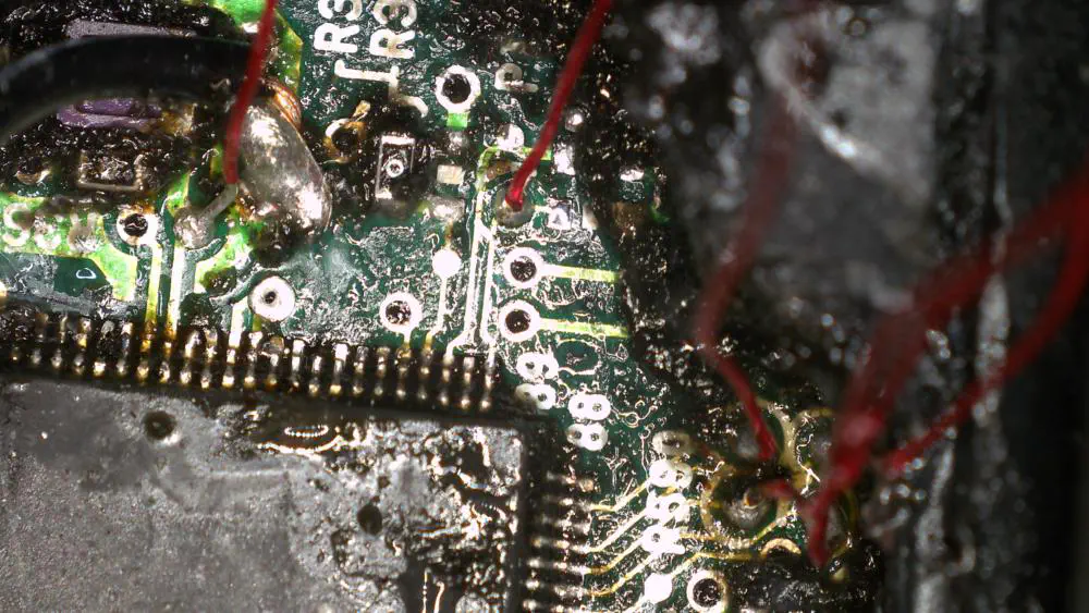
I used a YIHUA 982-III soldering iron to connect 28 AWG magnet wire to the small test pads. During the process of depotting I accidentally damaged the crystal oscillator so the magnet wire on the left goes into EXTAL so we can send clock pulses to the microcontroller in place of the damaged oscillator. The second magnet wire to the left goes into TRST and the cluster of four test pads on the right are TMS, TDO, TDI, and TCK.
I soldered the magnet wire to larger jumper wires and ran them into a breadboard.

Selecting Test Hardware
We need a device to connect to the JTAG interface so I decided to program a NUCLEO-F072RB for this purpose. It is faster than my Arduino Uno at 48 MHz and uses 3.3V I/O which is what the JTAG interface on the SH72531 expects.
A better device would be an RP2040 because of its higher clock speed or any of the full Raspberry Pi SBCs.
The Code
The full code is available on GitHub. I’m not going to go into it in much detail as the code is self-documenting.

The Secret Registers
After some trial and error I was able to identify the true IR length as being 5 bits long (instead of 4 bits) and I found the following undocumented registers:
- IR 00101 selects a 130-bit DR
- IR 00111 selects a 130-bit DR
- IR 01011 selects a 32-bit DR
What is Next
I plan on revisiting this project a bit later. I think in order to actually reverse engineer what these registers do I’m going to need to overwrite the firmware on my ECU so I can determine when the system halts and how these registers affect the running program. Regardless, this project was a lot of fun, gave me a chance to put some theory into practice, and gave me an opportunity to write some hacking firmware for my NUCLEO.