A Raspberry Pi, Arduino Nano, and Four Water Pumps
Background
Two years ago my wife, my son, and I moved into a house that runs on well water. Normally, a modern well system looks something like the following:
                                │        ┌───────────┐
                                │        │           │
                                │        │           │
                                │        │ Pressure  │
                                │        │   Tank    │
                                │        │           │
                                │        │           │
                                │        └─────┬─────┘
                                │              │
                                │            ┌─┴─┐Power from Breaker
      Well Casing               │  ┌─────────┤   ├──────────────────
       ┌─────┐                  │  │ ┌───────┤   ├─────────────────►
       │     │                  │  │ │       └───┘Main Water Line
       │     │                  │  │ │   Pressure Switch
───────┼─────┼──────────────────┴──┼─┼────────────────────────────────
       │     │                     │ │
       │ ┌───┼─────────────────────┘ │
       │ │ ┌─┼───────────────────────┘
       │ │ │ │
       │ │ │ │
       │ │ │ │
       │ │ │ │
       │ │ │ │
       │ │ │ │
       │ │┌┼┐│
       │ ││▲││ Check Valve
       │ ▼└┼┘│
       │┌──┴┐│
       ││   ││
       ││   ││ Well
       ││   ││
       ││   ││
       │└───┘│
       └─────┘
Water is stored in a bladder inside of a pressure tank. Surrounding the bladder is pressurized air that is constantly pressing on the water bladder and trying to push it out of the tank. Whenever a valve from the home’s water line is opened, like a sink or a shower valve, water is allowed to be pushed out of the pressure tank. A pressure switch monitors the water pressure of the whole system and if it observes the water pressure drop below a certain level (usually 40 PSI), it will close a circuit to power up the well. The well will then pump water out of the ground and fill the pressure tank until it reaches the pressure switch cutoff (usually 60 PSI).
The whole system is simple, but it only works if your one well produces more water than you consume. Rather than a high yield well, our home has three separate low-medium yield wells. The original setup looked like this:
                                                   │
                                                   │
                                           ▲       │
                                           │       │
                 ┌─────────┐               │Main   │
     Water Tank  │ ┌─────┐ │               │Water  │
 ┌───────────────┼─┼──┐  │ │┌───────────┐  │Line   │
 │               │ │  │  │ ││           │  │    ┌──┤
 │               │ │  │  │ ││           │  │    │  │Breaker
 │               │ │  │  │ ││ Pressure  │  │    │  │Panel
 │               │┌┼┐ │  │ ││   Tank    │  │ ┌──┤  │
 │               ││▲│ │  │ ││           │  │ │  │  │
 │               ▼└┼┘ │  │ ││           │  │ │  │  │
 │              ┌──┴┐ │  │ │└─────┬─────┘  │ │  └──┤
 │   Submersible│   │ │  │ │      │        │ │     │
 │          Pump│   │ │  │ │    ┌─┴─┐      │ │     │
 │              │   │ │  │ └────┤   ├──────┼─┘     │
 │              │   │ │  └──────┤   ├──────┘       │
 │              └───┘ │         └───┘              │
─┴────────────────────┴────────────────────────────┴─
─────────────────────────────────────────────────────
Rather than pressurizing the house’s main water supply directly from the well, a submersible pump inside of a large unpressurised tank in the basement pushed water into the pressure tank.
To fill the unpressurized water tank, float switches inside of it would control different wells. To protect the wells when they ran dry, some outdated current cutoff controllers were placed between the float switches and the wells themselves. When a well runs dry the current to it drops. These controllers would try to detect that current drop and shut off the well to prevent it from damaging itself.
                     │
  S Well ────────────┼─────────────────────────────┬───────┐
                     │    Well Controllers         │       │
                     │         ┌───┐               │       │      │
S/W Well ────────────┼─────────┤   ├─────────────┬─┼─────┐ │      │
                     │         └───┘             │ │     │ │      │
                     │         ┌───┐             │ │     │ │      │
  W Well ────────────┼─────────┤   ├───────────┬─┼─┼───┐ │ │      │
                     │         └───┘           │ │ │   │ │ │      │
                     │          ┌──────────────┼─┼─┼─┐ │ │ │      │
                     │          │              │ │ │ │ │ │ │   ┌──┤
                     │          │   ┌─┐────────┘ │ │ │ │ │ │   │  │Breaker
                     │          │   └─┘          │ │ │ │ │ └───┤  │Panel
                     │          │   ┌─┐──────────┘ │ │ │ └─────┤  │
                     │          │   └─┘            │ │ └───────┤  │
                     │          │   ┌─┐────────────┘ │         │  │
                     │          │   └─┘              │         └──┤
                     │          │   Float switches   │            │
                     │          │                    │            │
                     │          │                    │            │
                     │          │                    │            │
                     │          │                    │            │
                     │         ─┴────────────────────┴────────────┴─
               ──────┴──────────────────────────────────────────────
Issues With the Old System
It quickly became apparent that the original system worked poorly:
For some mysterious reason the south well had no current cutoff controller.
The wells that did have cutoff controllers were often cut off before running out of water and occasionally failed to cutoff after running dry.
If the water level in the tank got too low, nothing would prevent the tank pump from running dry and making an awful grinding noise as it slowly destroyed itself.
The Idea
After a few weeks of struggling with the water system, it became apparent that something this complex needed to be computer-controlled. I knew that home automation projects often use relays to allow low-voltage microcontrollers to control 120V/240V household loads. This seemed like a good way to control both the tank and well pumps.
I needed a few sensors to detect the well conditions and water tank level. For well conditions, I could use passive current transformers wrapped around the wires powering the wells and some basic circuitry to measure the current and convert it into a low-voltage analog signal. For the water tank level, I decided to use a Maxbotix EZ1 ultrasonic sensor I already had as a way to measure the water level in the unpressurised tank.
For the brains of the operation I wanted something that could send me notifications through Nextcloud Chat. Network communications like this are usually beyond the capabilities of a microcontroller so I needed an SBC. I had a spare Raspberry Pi 3 so I chose that. The Raspberry Pi 3 is powerful, but it lacks the ability to read analog voltages. Additionally, SBCs with full-blown operating systems are a lot more likely to hang or crash because of their complexity. Directly controlling wells with one could result in a well getting stuck in an on state. For this reason, I decided to use an Arduino Nano Every for all the low-level controls and interfacing. The Raspberry Pi would make high-level decisions and send notifications, while the Arduino would handle measuring current, switching the wells on and off, getting readings from the ultrasonic sensor, and performing a lot of the critical well protection logic.
Hardware Layout
First, I soldered some headers to a protoboard to mount the Arduino Nano Every and built some circuits around it.
I built four duplicate circuits to convert the current from the coil transformers to low-voltage outputs that connect to the Arduino analog inputs.
For tank level sensing, the Maxbotix EZ1 has an analog, serial, and PWM output. The most reliable choice was serial, but despite outputting TTL voltages that are in the correct range for the Arduino Nano Every (0-5V), the EZ1 outputs them inverted. So the last circuit on the protoboard is a simple NOT gate using an NPN transistor and some resistors to uninvert the signal before passing it to one of the hardware UART inputs on the Arduino.
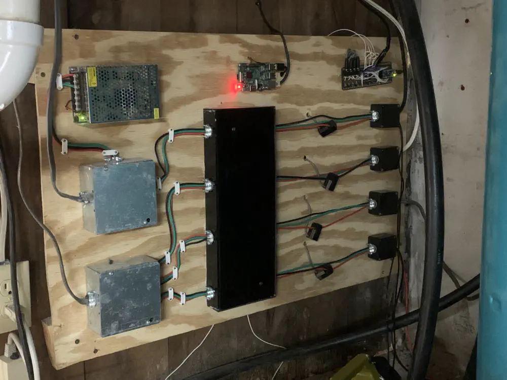
After building the protoboard, I arranged it, along with all the other components, on a large sheet of plywood.
        ┌───────────────────────────────────────────────────────┐
        │                                                       │
        │ ┌───────────┐      ┌──────────┐       ┌─────────────┐ │
        │ │           │ 5V   │          │ 5V &  │ Arduino +   │◄┼── Ultrasonic Sensor
        │ │ 5V Supply ├─────►│ RPi 3B   │◄─────►│ Protoboard  │ │
        │ │           │      │          │ UART  │             │◄┼── Pressure Switch
        │ └───────────┘      └──────────┘       └─────────────┘ │
        │       ▲                                      ▲▲▲▲     │
        │       │                                  ┌───┘│││     │
        │       │              ┌─────┐           ┌─┴──┐ │││     │
 240V ──┼───────┴─────────────►│Relay├───────────│Coil├─┼┼┼─────┼──► Tank Pump
        │                      └─────┘           └────┘ │││     │
        │                                          ┌────┘││     │
        │                      ┌─────┐           ┌─┴──┐  ││     │
        │    ┌────────────────►│Relay┼───────────┤Coil├──┼┼─────┼──► N Well
        │    │                 └─────┘           └────┘  ││     │
        │    │                                     ┌─────┘│     │
        │    │                 ┌─────┐           ┌─┴──┐   │     │
 240V ──┼────┼────────────────►│Relay├───────────┤Coil├───┼─────┼──► S/W Well
        │    │                 └─────┘           └────┘   │     │
        │    │                                     ┌──────┘     │
        │    │                 ┌─────┐           ┌─┴──┐         │
        │    └────────────────►│Relay├───────────┤Coil├─────────┼──► S Well
        │                      └─────┘           └────┘         │
        └───────────────────────────────────────────────────────┘
A 240V AC to 5V DC power supply powers the electromechanical relays as well as the Raspberry Pi. The Raspberry Pi connects to the Arduino using a simple USB-A to micro-USB cable to power the Arduino as well as establish serial communication without having to level-shift Raspberry Pi GPIO pins.
Safety Interlocks
There’s always a chance that the Arduino itself malfunctions or the firmware I wrote has bugs, so I wanted some basic protections to reduce the chance of a failure causing serious issues.
The pressure switch closes two sets of contacts. One of these contacts pulls a normally-high pin on the Arduino Nano to ground so that it can detect when to activate the tank pump relay. A major concern here is the tank pump running for too long and overpressurizing the system. This could result in our filtration system getting blown apart, our pressurized water lines breaking, water valves getting damaged, etc. To prevent this, the tank pump is wired in series with the other contacts on the pressure switch. Both the pressure switch and the tank pump relay have to be active before the tank pump will power on. This isn’t a perfect solution as the pressure switch is still a single point of failure and ideally the Arduino would use a completely separate sensor to detect water pressure. This does at least prevent faulty firmware on the Arduino from locking up and overpressurizing the system though.
The other concern I had was the ultrasonic sensor failing and the system continuing to run the wells, potentially flooding the basement after overfilling the tank. To fix this, I wired a float switch sitting in the tank in series with the 240V cable that gets split up to power the different wells. This way, if the water level gets too high the float switch will open and prevent the wells from running no matter what state the well relays are in.
Code
The full code for this project can be found here.
The code written on the Raspberry Pi is in Rust. A better choice would have been Python as the firmware running on the Pi does not need to be particularly fast. However, I like Rust and wanted to do it that way.
The firmware for the Arduino was written in C++. Because the Arduino is connected over USB to the Raspberry Pi, I was able to ssh into the Pi, write/compile the firmware, and upload it to the Arduino directly using arduino-cli.
Conclusion
This system was originally implemented in 2023, nearly two years ago from the time of this writing and it has massively improved the reliability of our water supply. I get notified of issues before our water cuts out, all four pumps are protected against running dry, and the system properly balances water usage across the three wells.